
Description
In 2009 John Berndt coined and defined the term Relabi in his essay “Relabi”: Patterns of Self-Erasing Pulse. These are his own words: “Relabi, Def.: The experience of a palpably coordinated plurality of events that appears to be cyclical but simultaneously suspends identification of a uniform pattern, preventing a resolved sense of pulse. Relabi therefore seems equally pulsed and unpulsed at the same time. It is an experiential gestalt, a quality of experience, greater than the sum of its parts (it forms a sustained unity in experience, albeit of a new kind).”
He also makes the question: “Why would anyone want this Relabi experience? I maintain that much of what is exciting in musical forms involves an interplay between the setting up and denying of pulse expectations.”
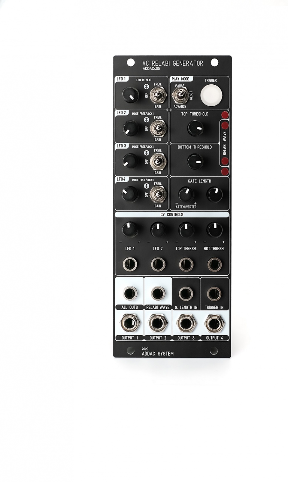
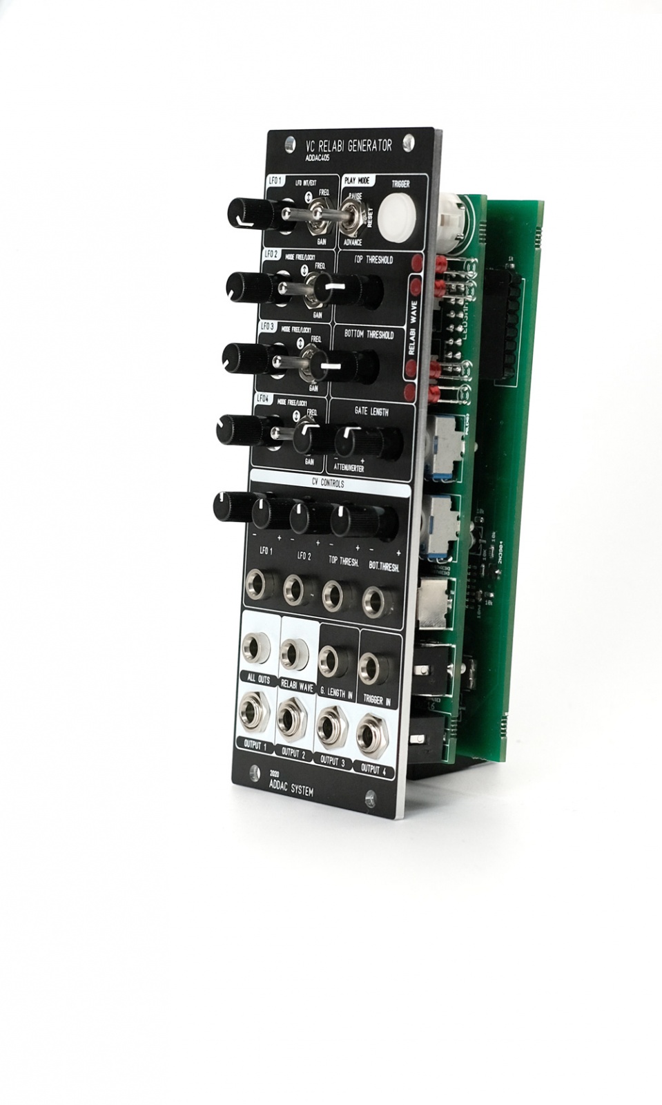
Inspired by this idea we developed this module that is both a gate/trigger and cv generator that can be freely used to trigger events or act as a complex modulation source. Four Sine LFOs are internally generated, each has controls for gain, frequency and mute(off). These 4 LFOs are then mixed together to generate what Berndt named the “Relabi Wave”. This “wave” becomes a complex bipolar CV source. This ±5v bipolar “wave” can be monitored on the 2 dedicated leds and is also available at its own Output.
Make sure to check the User's Guide for indepth description, working behaviour and diagrams.
This module will also be available as a full DIY kit.
Tech Specs:
10HP
4cm deep
100mA +12V
40mA -12V
Note: All specifications and features are subject to change without previous notice.
Videos
Firmware Update
Here's the procedure for updating your ADDAC405 Firmware
1. First you need to download this App:
https://www.pjrc.com/teensy/loader.html
2. Next download and unpack the Firmware file:
https://media.addacsystem.com/firmwares/ADDAC405_Firmware.zip
3. Open the App, go to: File>Open HEX File and choose the .hex file downloaded.
4. Remove your module from the frame but keep it connected to your busboard and keep power ON.
5. Find the micro usb connector located at the top of the module and plug a usb cable to your computer.
6. Look for a small white push button on the small board where the USB is connected to, use some plastic tool (metal may short some pins when reaching in) to reach in and press the button once.
7. On your computer hit upload on the teensy loader app, wait for it to complete and you're all done.
----------------------------------------------------------------------------------------------
Last update version: B_8, July, 23rd, 2021
B_8 Changes Log:
* FIXED: An issue where the channels Gain was not working and instead was locked at 1:1
Order
Thanks for your interest in the ADDAC405!
To proceed with a direct purchase, you may fill out the form on our Orders Page.
If you want to obtain it through a shop closer to you, this is our Distributors Page.
Custom Panel
In case you're wondering: Sure! We can get you a custom coloured front panel for the ADDAC405.
It has an additional cost and takes 4 to 6 weeks to be ready.
At the moment the ADDAC405 standard panel colour is Black.
A custom colour panel can be done in either Red, Green, Blue, White, Silver Gray, Yellowed Silver, and Dark or Light Bronze.
Print colour varies between Black, White, or Red, Blue and Green. We recommend lighter-tone print for darker panels, and vice-versa.
Please note: we don’t stock custom coloured panels. For every custom order we need to make a single panel order from our panel provider. This explains the panel price and lead time.
Product Safety Information
Product Safety Information
Eurorack Module
Important Safety Information
This Eurorack module is designed for use within standard Eurorack synthesizer systems and is intended for adult users familiar with modular synthesis and electronic equipment.
Please read this safety guide before installation or use.
General Warnings
1. Electrical Hazards:
• Ensure the power supply matches the module’s specified voltage and current ratings (refer to the product manual). Incorrect voltage can damage the module and pose a safety risk.
• Never connect or disconnect the module while the Eurorack system is powered on.
2. Heat Generation:
• The module may generate heat during operation. Ensure proper ventilation within your Eurorack case to prevent overheating.
3. Sharp Edges:
• The module’s faceplate and components may have sharp edges. Handle with care to avoid cuts or scratches.
4. Small Parts:
• Contains small parts that could pose a choking hazard. Keep away from children and pets.
5. Compatibility:
• This module is designed specifically for Eurorack-compatible systems. Connecting it to non-compatible systems may result in damage or malfunction.
Installation and Use
• Mounting: Secure the module properly in the Eurorack case using the provided screws.
• Power Connection: Verify the polarity of the power cable before connecting to avoid damage to the module or power supply. Use only the included or manufacturer-recommended power cable.
• Operational Use: Follow the module's user guide for instructions on operation. Do not exceed the input/output limits specified.
Maintenance and Handling
• Inspection: Regularly check for loose connections or signs of wear.
• Cleaning: Disconnect the module from power before cleaning. Use a dry or lightly damp cloth; avoid using solvents or water directly on the module.
• Repairs: Do not attempt to repair or modify the module yourself. Contact the manufacturer for support.
Environmental Safety
• Dispose of the module, its components, and packaging in accordance with local electronic waste regulations.
Liability Disclaimer
• The manufacturer is not responsible for any injury, damage, or malfunction resulting from improper installation, use, or modification of this product.
Contact Information
For further assistance, contact our support team at:
Addacsystem, Lda.
addac[at]addacsystem[dot]com