
Description
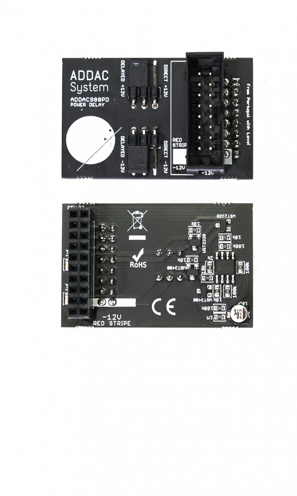
This small board was designed to bring some extra flexibility and customization regarding powering up a modular system.
Whenever a modular system is turned on there's a current spike upon startup that will momentarily influence the PSU output and can take up to a couple seconds for the PSU to stabilize to it's stated specifications. PSUs can also have some delay between their power lines where one polarity is provided prior to the second one. They also commonly have a ramp like startup. All this is common and normally not a problem. While most modules are fine with this situation, there are others that can suffer from this and in a worst case scenario won't startup correctly. Some modules can also be sensitive to the timing of the ±12v, some may require both to arrive at the same time others won't start if -12v arrives prior to the +12v, etc.
This small board allows to time the deployment of power to a specific module, it can delay each power line independently by 3 seconds, meaning that after powering up your modular it will wait for 3 seconds until it will provide power to the specific module connected to it. This delay time can also be customized by the user replacing a couple capacitors.
Using this small board with more sensitive modules allow them to power up at a time past the initial spike and where the PSU is already stable and it will guarantee that the ±12V is delivered at exactly the same time.
Besides this very technical use there are other creative and useful uses, for example plug it to those specific modules that "drive" your patch, like a sequencer or a clock and have them power up later so that other modules have time to start up and stabilize before starting up the clock. Go even deeper in this idea and have diferent 900PDs with diferent capacitors that will allow you to "program" a sequential module power up, useful for generative patches that run on a power timer in exhibitions and galleries.
One more useful hack is to use it in those cases where your frame won't power up due to the initial current "spike", making it going over its limits and trip the protection mechanism failing to startup. The usual "hack" is to unplug one or two modules allowing it to power up and then connect the extra modules in. ***Warning*** power up issues like these simply means your PSU is close to its maximum and the pcb shouldn't be used as a permanent fix and we advise upgrading the PSU. However it will make it easier in that situation where you add one last minute module for that gig in a few hours and that extra module trips the psu protection, then as a temporary hack the pcb will make it easier for the frame to power up at the gig.
There are 2 sets of jumpers to independently set the power line to be delayed, -12V, +12V or both.
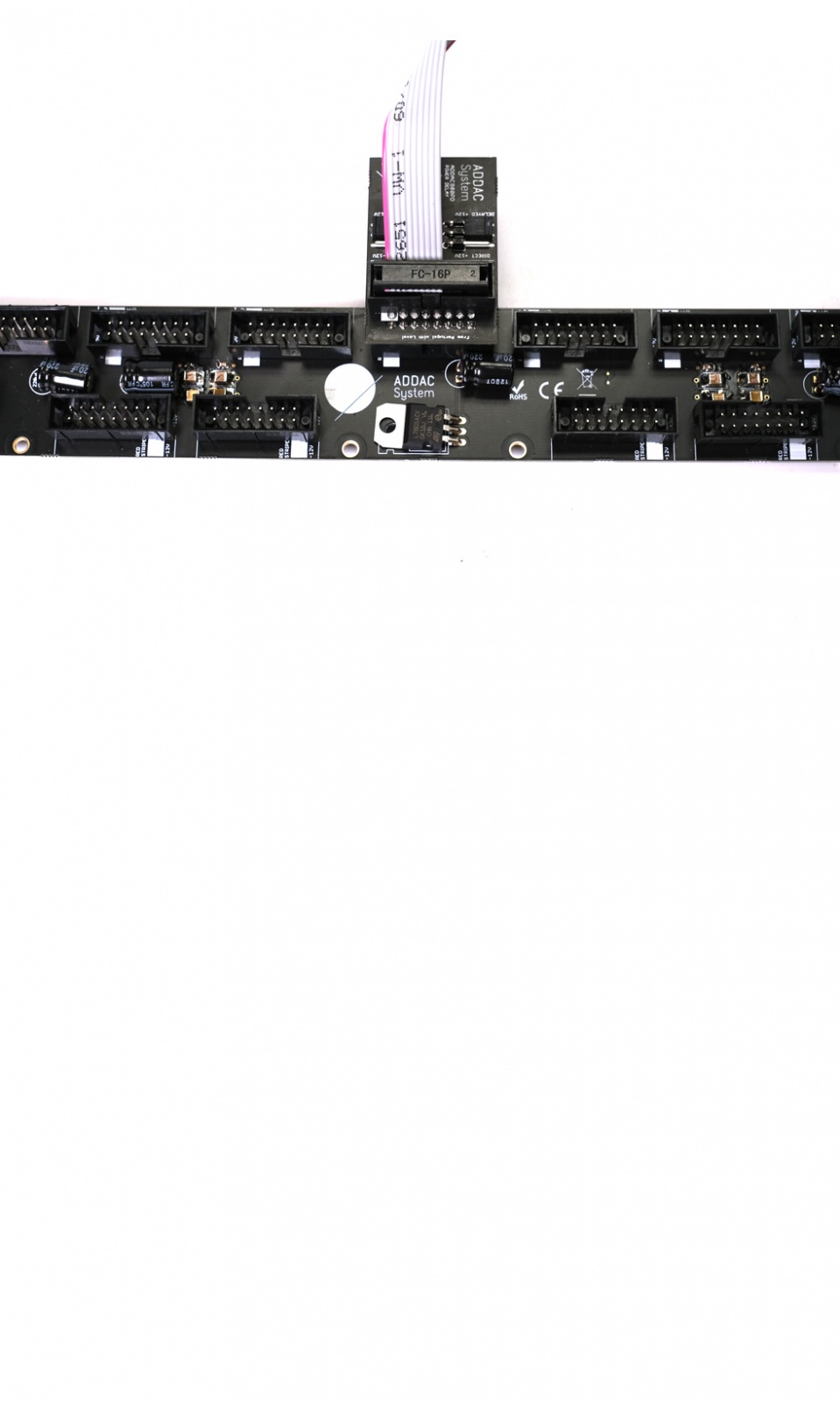
This pcb will be plugged onto your busboard and, in turn, allow a ribbon power cable to be connected to it.
There are 2 models ADDAC901PDO for Old style Busboards and ADDAC901PDN for New style Busboards
DISCLAIMER: Both the ADDAC901PDO and the ADDAC901PDN are not to be used with modules that require external +5V supply.
Note: All specifications and features are subject to change without previous notice.
Order
Thanks for your interest in the ADDAC900PDN!
To proceed with a direct purchase, you may fill out the form on our Orders Page.
If you want to obtain it through a shop closer to you, this is our Distributors Page.
Product Safety Information
Eurorack Busboard Module
Please read this safety guide before installation or use.
Intended Use
• This product is a Eurorack power supply module (busboard/distribution board) intended to supply Eurorack-compatible synthesizer modules with ±12V and +5V.
• It must be installed in a suitable Eurorack case by the end customer.
• The power supply works with an external plug-in or desktop power adapter (not always included). Only use a compatible adapter with the specified voltage, current, and polarity.
• Any use outside the intended application may result in malfunction, fire hazard, or electric shock.
Installation and Use
• Disconnect the external power adapter from mains before installation or maintenance.
• Mount the power supply securely inside the case using suitable screws and spacers to avoid mechanical stress or short circuits.
• Ensure correct polarity and orientation when connecting modules. Incorrect connection may damage modules or the entire system.
• Do not exceed the maximum current ratings for each power rail.
• Ensure sufficient ventilation inside the case to prevent overheating.
• Route cables carefully to avoid kinks, pinching, or contact with sharp edges.
• Only use original or manufacturer-approved external power adapters.
Warnings
• Risk of electric shock: the product operates with voltages supplied from mains-powered adapters. Never touch live contacts.
• Risk of fire: overloading, blocked ventilation, or defective components can cause overheating.
• Risk of damage: incorrect polarity or overvoltage may permanently damage modules or the power supply.
• Short circuit hazard: prevent contacts or busboard rails from touching conductive objects.
• Small parts may pose a choking hazard. Keep away from children and pets.
• Do not open, modify, or repair the product yourself. Improper handling may cause injury or permanent damage.
Storage and Cleaning
• Store the product in a dry, cool place away from moisture and extreme temperatures.
• Disconnect the power adapter before cleaning.
• Clean with a dry cloth only. Do not use water or aggressive cleaning agents.
Responsibility
Users are solely responsible for proper assembly and testing. Contact manufacturer support for assistance if needed.
Environmental Safety
• Dispose of the module, its components, and packaging in accordance with local electronic waste regulations.
Liability Disclaimer
• The manufacturer is not responsible for any injury, damage, or malfunction resulting from improper installation, assembly, use, or modification of this product.
Contact Information
Addacsystem, Lda.
addac[at]addacsystem[dot]com
DIY Kit
The ADDAC900PDN is also available as a DIY Kit.
It costs 14€ (Excl. VAT).
To proceed with a direct purchase, you may fill out the form on our Orders Page.
If you want to obtain it through a shop closer to you, this is our Distributors Page.
Here's the detailed step by step Assembly Guide Pdf:
https://media.addacsystem.com/diy_guides/ADDAC900PD_DIYkit.pdf
DIY Kit Product Safety Information
DIY Kit for Eurorack Busboard Module
Please read this safety guide before installation or use.
Intended Use
• This product is a Eurorack power supply module (busboard/distribution board) intended to supply Eurorack-compatible synthesizer modules with ±12V and +5V.
• It must be installed in a suitable Eurorack case by the end customer.
• The power supply works with an external plug-in or desktop power adapter (not always included). Only use a compatible adapter with the specified voltage, current, and polarity.
• Any use outside the intended application may result in malfunction, fire hazard, or electric shock.
Assembly Requirements
• If supplied as a kit, the product is intended for adult users experienced in electronics and modular synthesis.
• Assembly, including soldering, is required.
• Ensure a clean, well-lit and ventilated workspace free of flammable materials during assembly.
• Use appropriate tools and safety equipment, such as eye protection.
Testing
• Test the module thoroughly for shorts or incorrect assembly before powering it in your Eurorack system.
• Incorrectly assembled modules may damage the entire Eurorack system. Test in a separate case with only the single module whenever possible.
• Use a multimeter or other appropriate tools to confirm proper functionality.
Installation and Use
• Disconnect the external power adapter from mains before installation or maintenance.
• Mount the power supply securely inside the case using suitable screws and spacers to avoid mechanical stress or short circuits.
• Ensure correct polarity and orientation when connecting modules. Incorrect connection may damage modules or the entire system.
• Do not exceed the maximum current ratings for each power rail.
• Ensure sufficient ventilation inside the case to prevent overheating.
• Route cables carefully to avoid kinks, pinching, or contact with sharp edges.
• Only use original or manufacturer-approved external power adapters.
Warnings
• Risk of electric shock: the product operates with voltages supplied from mains-powered adapters. Never touch live contacts.
• Risk of fire: overloading, blocked ventilation, or defective components can cause overheating.
• Risk of damage: incorrect polarity or overvoltage may permanently damage modules or the power supply.
• Short circuit hazard: prevent contacts or busboard rails from touching conductive objects.
• Small parts may pose a choking hazard. Keep away from children and pets.
• Do not open, modify, or repair the product yourself. Improper handling may cause injury or permanent damage.
Storage and Cleaning
• Store the product in a dry, cool place away from moisture and extreme temperatures.
• Disconnect the power adapter before cleaning.
• Clean with a dry cloth only. Do not use water or aggressive cleaning agents.
Responsibility
Users are solely responsible for proper assembly and testing. Contact manufacturer support for assistance if needed.
Environmental Safety
• Dispose of the module, its components, and packaging in accordance with local electronic waste regulations.
Liability Disclaimer
• The manufacturer is not responsible for any injury, damage, or malfunction resulting from improper installation, assembly, use, or modification of this product.
Contact Information
Addacsystem, Lda.
addac[at]addacsystem[dot]com