
Description
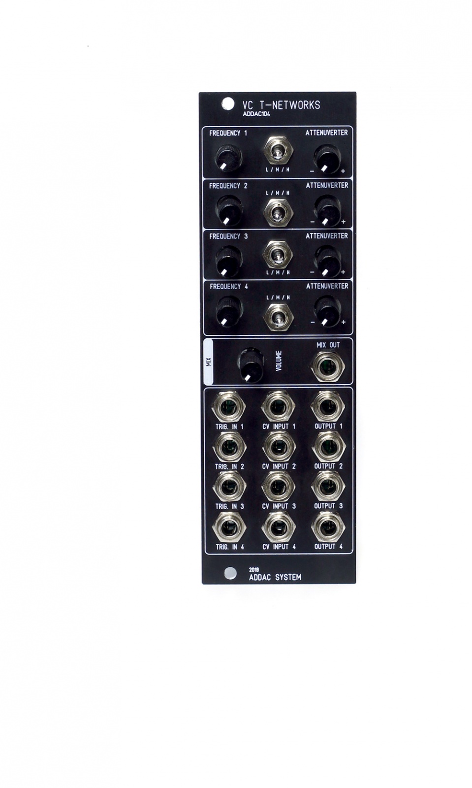
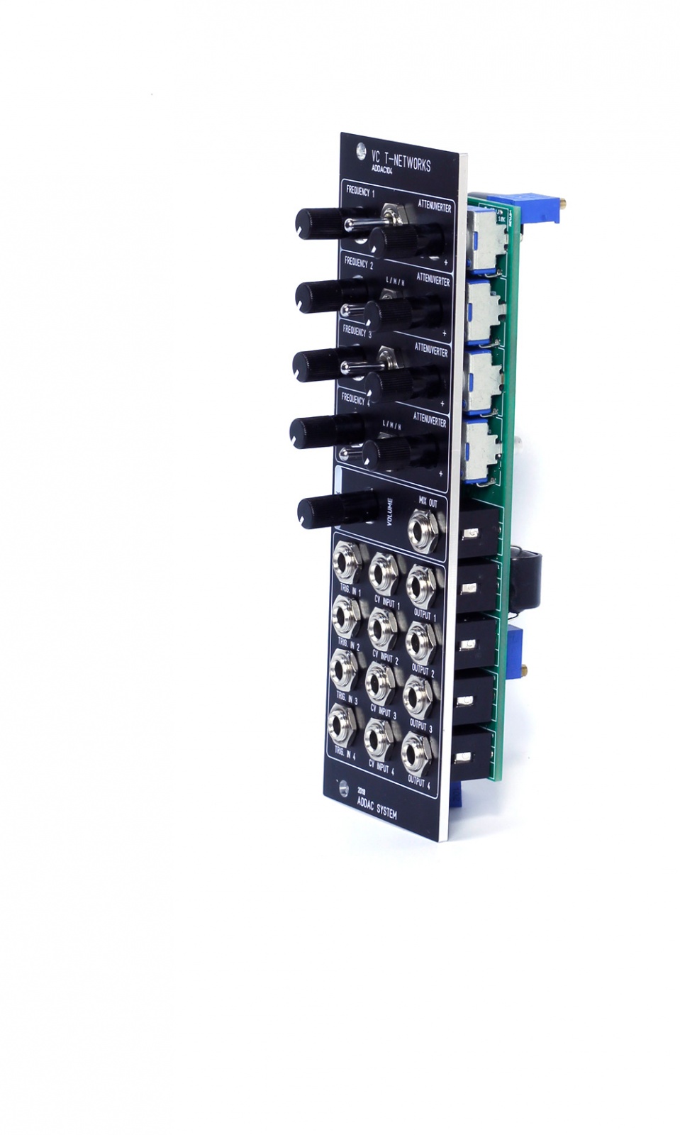
Following our ADDAC103 T-Networks this new module is also inspired by Twin T-Networks circuits used in many legendary drum machines. A simple 4 voice module with frequency controls for each of the voices. This new module also features CV inputs with attenuverters for each voice Frequency. Due to the specificities of the circuit and to keep the module at a low price these inputs are not calibrated to 1v/octave.
At each voice input there’s a gate to trigger converter so any input source is possible.
Audio inputs can also be used as an input, in this case and due to the nature of the gate to trigger converter, each voice can be used as very destructive filters.
The top 2 channels feature a higher frequency range, the bottom 2 channels feature a lower frequency range.
Features;
4 Voices each with:
Frequency control with CV input and attenuverter Frequency Range Switch, Low/Mod/High
Trigger Input
Audio Output
Summing Mix output with Volume control
-
This module is also available as a full DIY kit.
Specs:
8Hp
2.5cm deep
50mA +12v
50mA -12v
Note: All specifications and features are subject to change without previous notice.
Media
Custom Panel
In case you're wondering: Sure! We can get you a custom coloured front panel for the ADDAC104.
It has an additional cost and takes 4 to 6 weeks to be ready.
A custom colour panel can be done in either Red, Green, Blue, White, Silver Gray, Yellowed Silver, and Dark or Light Bronze.
Print colour varies between Black, White, or Red, Yellow, Blue and Green. We recommend lighter-tone print for darker panels, and vice-versa.
Please note: we don’t stock custom coloured panels. For every custom order we need to make a single panel order from our panel provider. This explains the panel price and lead time.
Order
Thanks for your interest in the ADDAC104!
To proceed with a direct purchase, you may fill out the form on our Orders Page.
If you want to obtain it through a shop closer to you, this is our Distributors Page.
Product Safety Information
Product Safety Information
Eurorack Module
Important Safety Information
This Eurorack module is designed for use within standard Eurorack synthesizer systems and is intended for adult users familiar with modular synthesis and electronic equipment.
Please read this safety guide before installation or use.
General Warnings
1. Electrical Hazards:
• Ensure the power supply matches the module’s specified voltage and current ratings (refer to the product manual). Incorrect voltage can damage the module and pose a safety risk.
• Never connect or disconnect the module while the Eurorack system is powered on.
2. Heat Generation:
• The module may generate heat during operation. Ensure proper ventilation within your Eurorack case to prevent overheating.
3. Sharp Edges:
• The module’s faceplate and components may have sharp edges. Handle with care to avoid cuts or scratches.
4. Small Parts:
• Contains small parts that could pose a choking hazard. Keep away from children and pets.
5. Compatibility:
• This module is designed specifically for Eurorack-compatible systems. Connecting it to non-compatible systems may result in damage or malfunction.
Installation and Use
• Mounting: Secure the module properly in the Eurorack case using the provided screws.
• Power Connection: Verify the polarity of the power cable before connecting to avoid damage to the module or power supply. Use only the included or manufacturer-recommended power cable.
• Operational Use: Follow the module's user guide for instructions on operation. Do not exceed the input/output limits specified.
Maintenance and Handling
• Inspection: Regularly check for loose connections or signs of wear.
• Cleaning: Disconnect the module from power before cleaning. Use a dry or lightly damp cloth; avoid using solvents or water directly on the module.
• Repairs: Do not attempt to repair or modify the module yourself. Contact the manufacturer for support.
Environmental Safety
• Dispose of the module, its components, and packaging in accordance with local electronic waste regulations.
Liability Disclaimer
• The manufacturer is not responsible for any injury, damage, or malfunction resulting from improper installation, use, or modification of this product.
Contact Information
For further assistance, contact our support team at:
Addacsystem, Lda.
addac[at]addacsystem[dot]com
DIY Kit
The ADDAC104 is also available as a DIY Kit.
It costs 154€ (Excl. VAT).
To proceed with a direct purchase, you may fill out the form on our Orders Page.
If you want to obtain it through a shop closer to you, this is our Distributors Page.
Here's the detailed step by step Assembly Guide Pdf:
http://media.addacsystem.com/diy_guides/ADDAC104_DIYkit.pdf
Troubleshooting
Usually there are 3 building mistakes with the ADDAC104 DIY builds:
.1 - The vactrols polarity is reversed.
First, get familiar with the lm78l05 pinout (here); locate the output pin and the ground pin and check with your multimeter if the output pin delivers a voltage around 5v. To do this, set the multimeter to DC voltage and point the black probe to ground pin and the red probe to the output pin. If you read a voltage around 5v the LM78l05 is fine.
.2 - The user did not calibrate the trimmers properly.
To calibrate the trimmers, keep in mind that these are 20-turn trimmers and they only affect the vactrols on a very short range of turns. First set the switch to middle or low position, turn the potentiometer full clockwise and start turning the trimmer that is related to that channel. Turn it anti-clockwise until you hear the “bongo” sound. If you turned the trimmer all the way to the end and nothing happened, started turning the trimmer clockwise. Since your potentiometer is fully clockwise, tune to the highest pitch possible on the trimmer.
.3 - The user plugged the power in reverse and the lm78l05 is dead.
Check again vactrol polarity; if the vactrols are reversed nothing will work.
DIY Kit Product Safety Information
DIY Kit for Eurorack Module
Please read this safety guide before installation or use.
Important Notice & Intended Use
• This kit is intended for adult users experienced in electronics and modular synthesis.
• Assembly, including soldering, is required.
• Proper testing and installation are essential to ensure safe and functional operation.
• The completed module is intended for installation in a Eurorack-compatible synthesizer system powered by ±12V and +5V.
• Use outside this scope may result in malfunction, damage, or safety risks.
General Warnings
Electrical Hazards:
• Ensure the power supply matches the module’s specified voltage and current ratings (refer to the product manual). Incorrect voltage can damage the module and pose a safety risk.
• Never connect or disconnect the module while the Eurorack system is powered on.
• Wrong polarity can damage your module or system. Make sure the module is connected with correct polarity.
Heat Generation:
• The module may generate heat during operation. Ensure proper ventilation within your Eurorack case to prevent overheating.
Sharp Edges:
• The module’s faceplate and components may have sharp edges. Handle with care to avoid cuts or scratches.
Small Parts:
• Contains small parts that could cause a choking hazard. Keep away from children and pets.
Compatibility:
• This module is designed specifically for Eurorack-compatible systems. Connecting it to non-compatible systems may result in damage or malfunction.
Assembly Requirements
• Soldering skills are required to complete the module.
• Ensure a clean, well-lit and ventilated workspace free of flammable materials during assembly.
• Use appropriate tools and safety equipment, such as eye protection.
Testing
• Test the module thoroughly for shorts or incorrect assembly before powering it in your Eurorack system. When the unit has malfunctions due to incorrect assembly, the entire Eurorack system might be damaged. It's a good idea to test it in a separate case with only that single module.
• Use a multimeter or other appropriate tools to confirm proper functionality.
Installation and Use
• Mount securely in a Eurorack case using the provided screws.
• Use only the included or manufacturer-recommended power cable.
• Connect only when the power is off.
• Follow the module's user guide for instructions on operation. Do not exceed the input/output limits specified.
Responsibility
Users are solely responsible for proper assembly and testing. Contact manufacturer support (see below) for assistance if needed.
Environmental Safety
• Dispose of the module, its components, and packaging in accordance with local electronic waste regulations.
Liability Disclaimer
• The manufacturer is not responsible for any injury, damage, or malfunction resulting from improper installation, use, or modification of this product.
Contact Information
Addacsystem, Lda.
addac[at]addacsystem[dot]com